This page shows the setup using detectors with high gain, such as PMTs and Channel electron multipliers. Faraday cup detection falls into a slightly different category, because the size of the signal can vary significantly.
Connecting a PMT to the CSP:
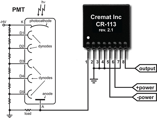
The connection scheme of a photomultiplier tube to a CSP is shown below:

This PMT biasing scheme directly connects the anode to the input of the preamplifier. In the case where the biasing of the PMT is made with the photocathode at ground and the anode at positive bias, then a HV blocking capacitor is necessary between the anode and the preamplifier input.
A PMT based detection setup
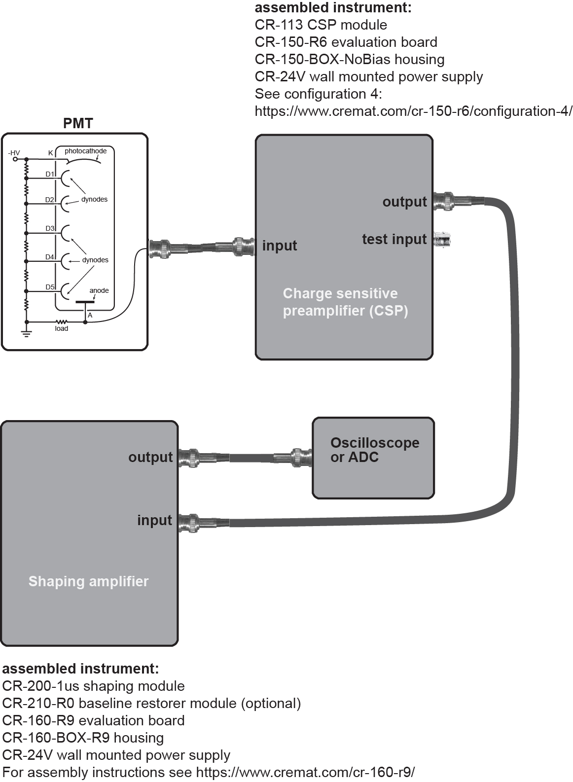
An overview of the instrumentation for a PMT detection setup is shown below. We recommend keeping the cable between the PMT and CSP as short as possible.

helpful links:
https://www.cremat.com/cr-150-r6/configuration-4/
https://www.cremat.com/cr-160-r9/
Choice of shaping time in the shaping amplifier
In the diagram above, the shaping amplifier uses a 1 microsecond shaping time, and is a 'middle of the road' choice for many applications. There are, however, some guidelines to help you determine the best shaping time for your application:
1) Choose a shaping time that is long enough to collect all the charge from the PMT. While PMTs are fast detectors, the photon signal may have a duration lasting microseconds. For example, detection of a light signal from a CsI(Tl) scintillator occurs over a 2 microsecond duration. In this case and in other applications involving relatively slow signals, use a shaping time that is at least as long as the photon signal duration.
2) Choose a shaping time that is short enough to accommodate the expected counting rate of the detection system.
Connecting to a Faraday cup or Channel electron multiplier (CEM):
The setup for a CEM is similar to that shown in the PMT setup above and the parts and assembly should be similar. After assembly, simply attach the anode to the CSP input. Because of the large gain of the CEM, a low gain CSP (such as the CR-113) should be used.
For Faraday cup applications, the same setup and assembly can again be used, but because the choice of the CSP module depends on the size of the expected signal. Guidelines for the choice of CSP can be found here.