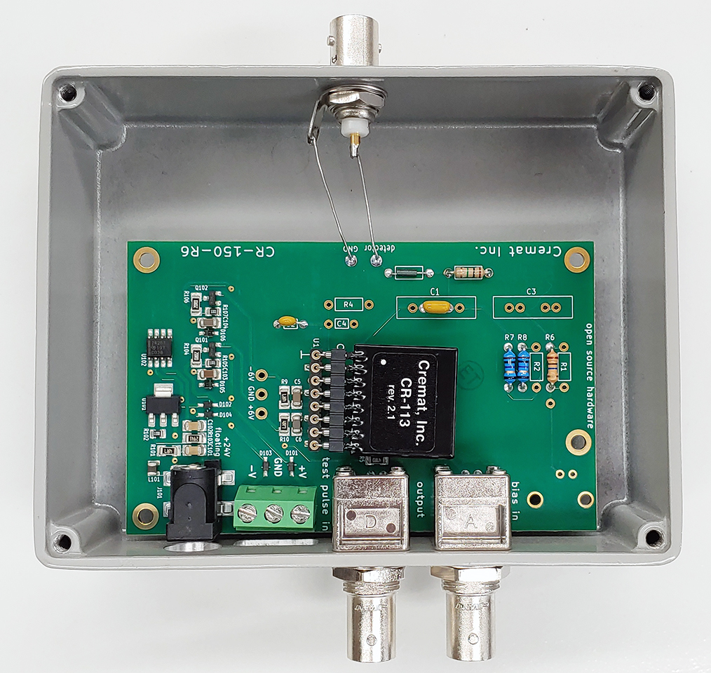
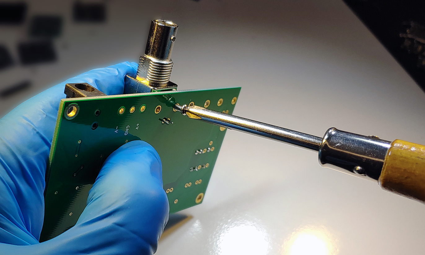
This page describes how to assemble the CR-150-R6 board in 'configuration 4'. This configuration installs the CR-150-R6 board into the CR-150-BOX-NoBias housing. This configuration is used for detectors such as photomultiplier tubes, Faraday cups, and channel electron multipliers - Detectors with no preamplifier-based biasing requirements.
You will need a soldering iron with solder and flux, a Phillips screwdriver with wide handle, an adjustable wrench, a soft toothbrush to clean the soldered boards, and an oven (100C) to dry the cleaned boards.
Start with the CR-150-R6 board:
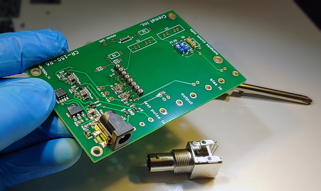
Install BNC connectors:
Place the two wires of one of the panel mount BNC connectors in the 'test input' position:
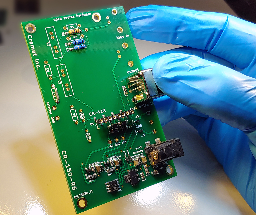
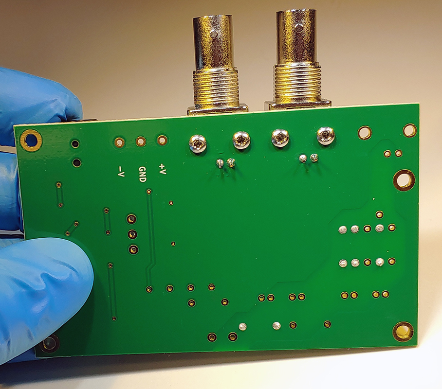
Use a Phillips screwdriver to screw the (included) 2-56 self tapping screws into the connector. Note: the screw holes in the BNC connectors do not come already tapped. The self tapping screws form their own threads in the hole when being inserted. More information on self tapping screws can be found here. Do not try to use a thin jeweler's screwdriver to insert the screws as you will need a screwdriver with a wide handle to properly apply the needed torque.
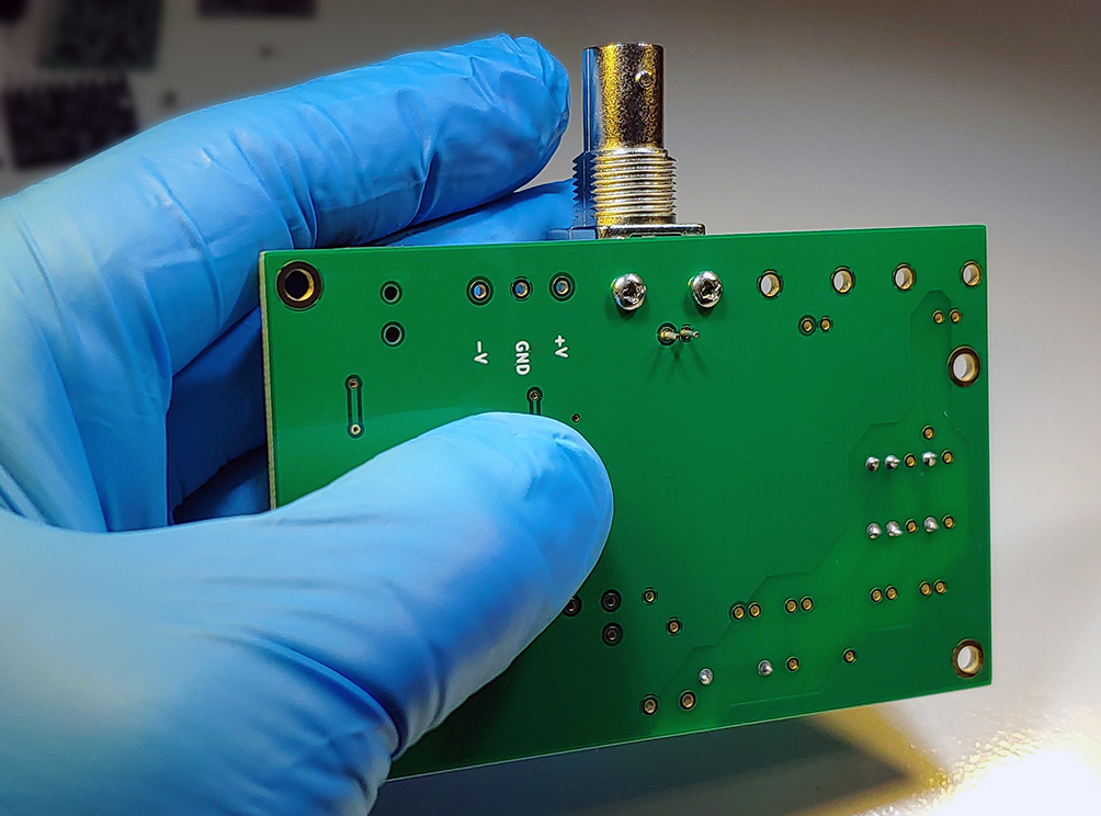
Do the same thing for the output connector. Solder the leads onto the board. Do not install a BNC connector at the 'bias in' position.
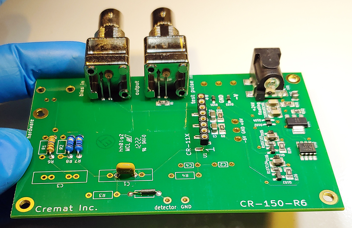
Install blocking capacitor
Install one of the yellow-colored 1uF capacitors to the C1 position. C3 is not used in this configuration.
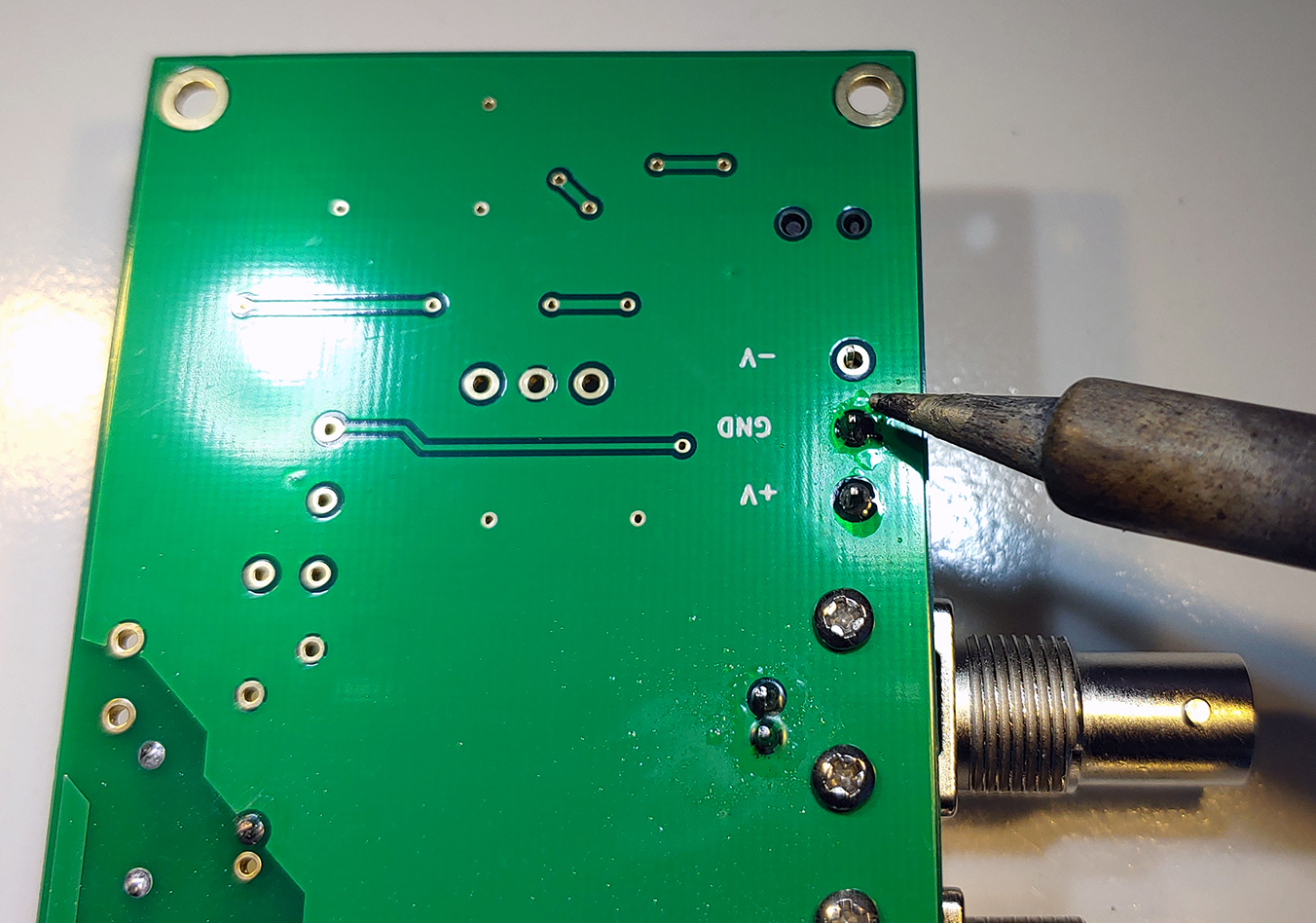
Install the 3-position terminal block
If you are going to be installing the CR-150-R6 board into the CR-150-BOX-D-Sub or CR-150-BOX-D-Sub-HV then install the terminal block onto the bottom side of the board with the wire entry side facing back. Otherwise install onto the top side of the board as in the photo.
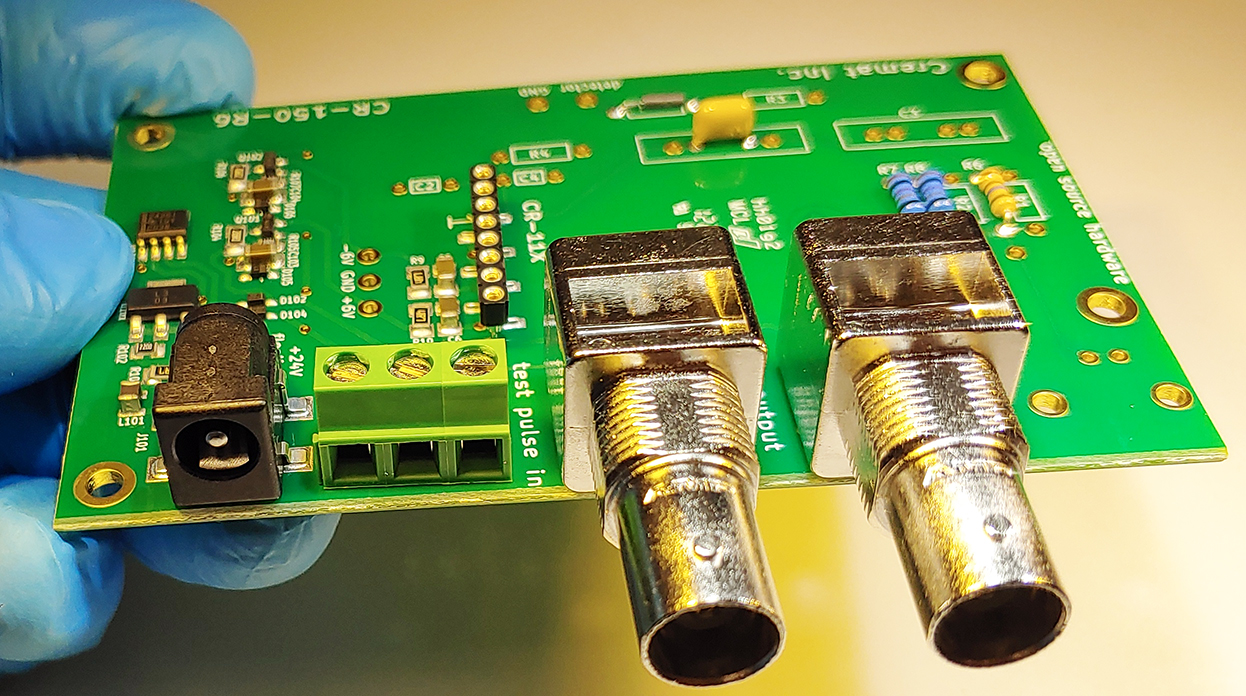
And solder it into place:
Install the test input coupling capacitor
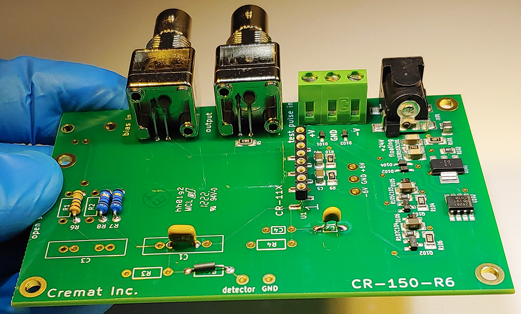
If the detector is a Faraday cup and either the CR-110 or CR-111 preamplifier will be used, install and solder into place the 1pF (blue) test coupling capacitor to C2. If using the CR-113 preamplifier (as you would with a PMT or channel electron multiplier), install the 10pF capacitor (yellow) to C2. The photo below shows the installation of a 10pF test coupling capacitor.
Install the 'load resistor' R3 and solder wires to the 'input' terminals
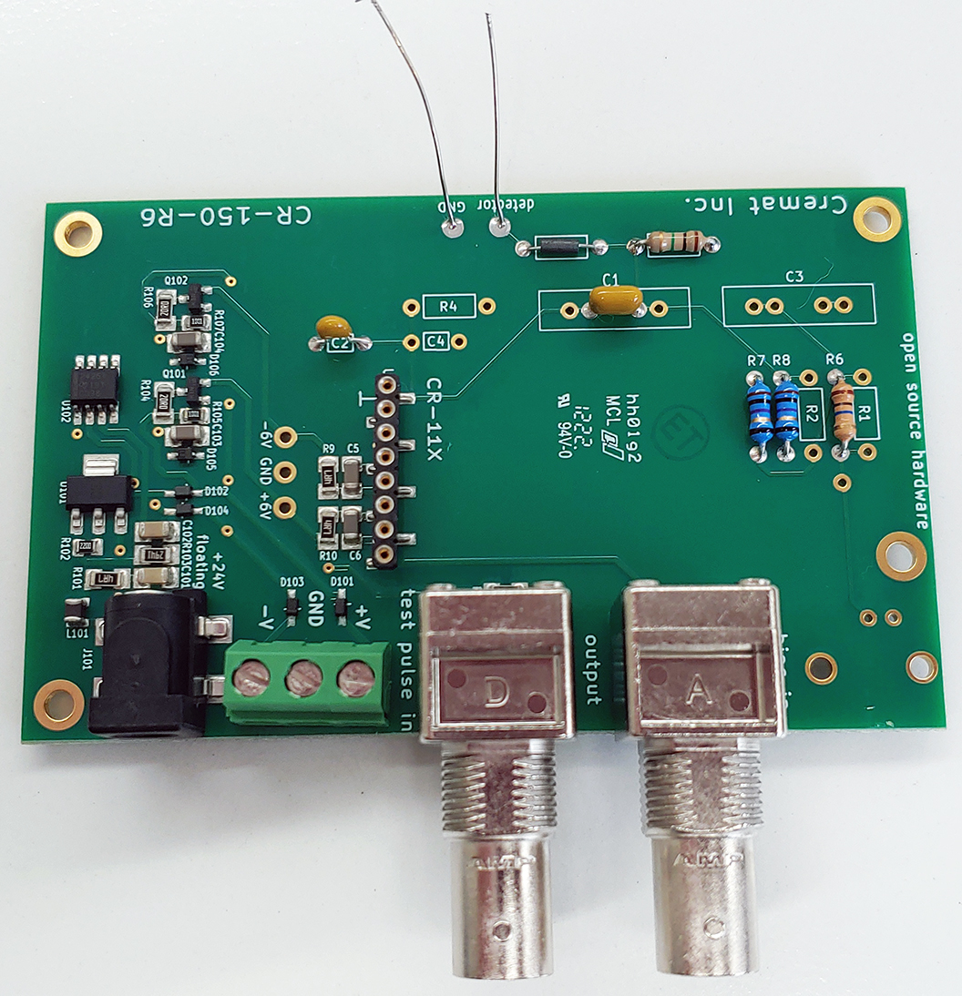
This configuration has a 1Megohm resistor from the preamplifier input to ground to act as a load resistor for the PMT/channel electron multiplier/Faraday cup. Install and solder into place the 1M resistor to R3.
Also, install and solder into place two 2-inch (5cm) wires onto the 'detector' and 'GND' positions.
Clean the board
Soldering on the board is completed! Clean off the residual flux. If you used rosin flux then you will need isopropyl alcohol to clean it. Water soluble flux needs only hot water. Dry the board completely before advancing (1hr in a drying oven at 100C).
Install the board into shielded housing CR-150-BOX-NoBias
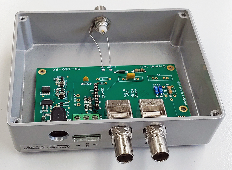
If you want to use the shielding housing (CR-150-BOX-no-bias), it is time to install into it. Place the board into the housing:
Place the lock washer and nuts onto the BNC connectors:
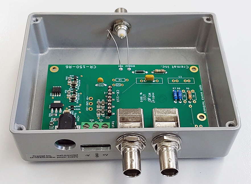
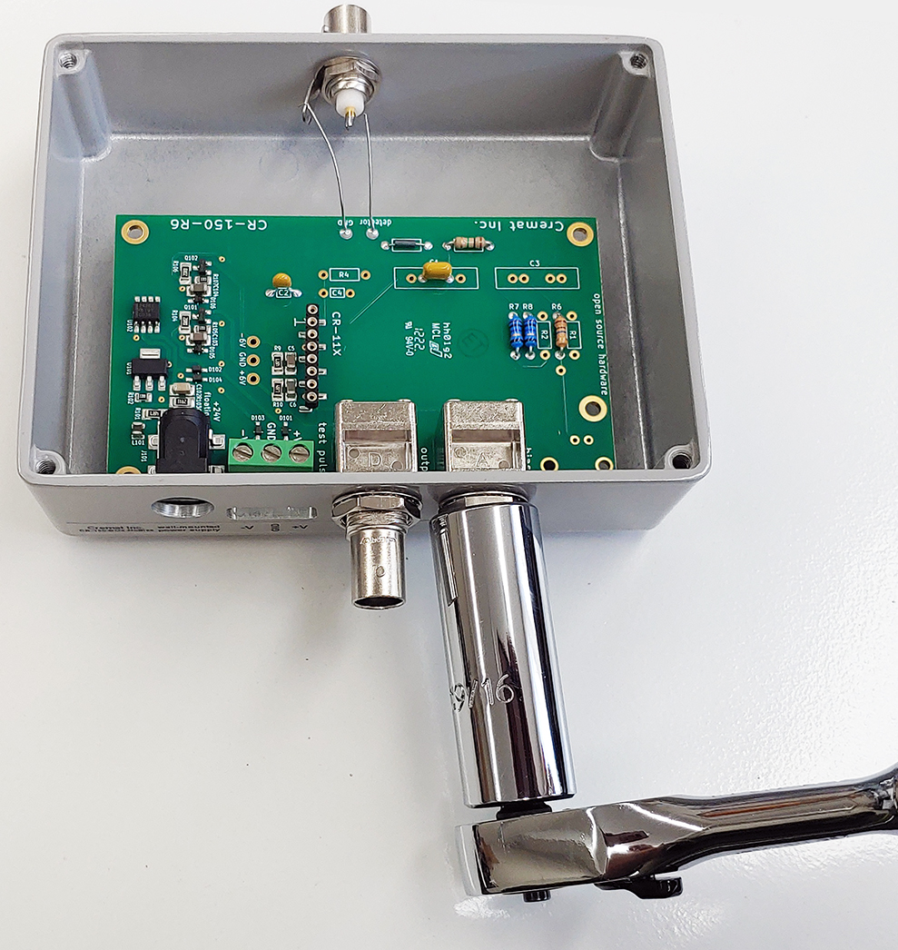
Tighten the nuts. A carefully-used adjustable wrench would be the best tool for this.
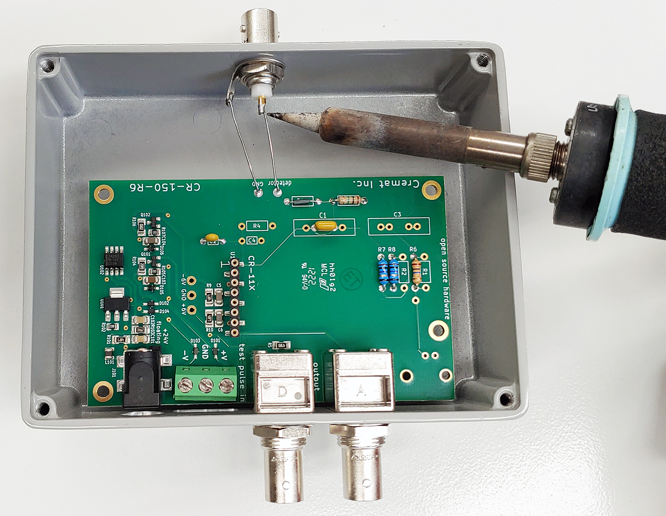
Final soldering
Solder the two wires onto the BNC connector after trimming their length. Also trim and solder into place the 1 inch wire connecting the bias supply to the board.
Install the CSP module
Install the CSP module onto the right angle adapter:
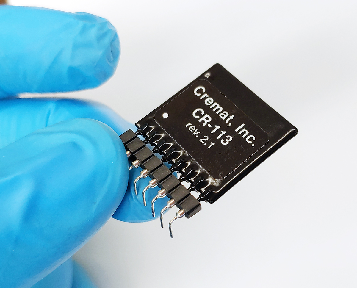
Push the adapter/CSP onto the 8 pin SIP socket on the CR-150-R6 board:
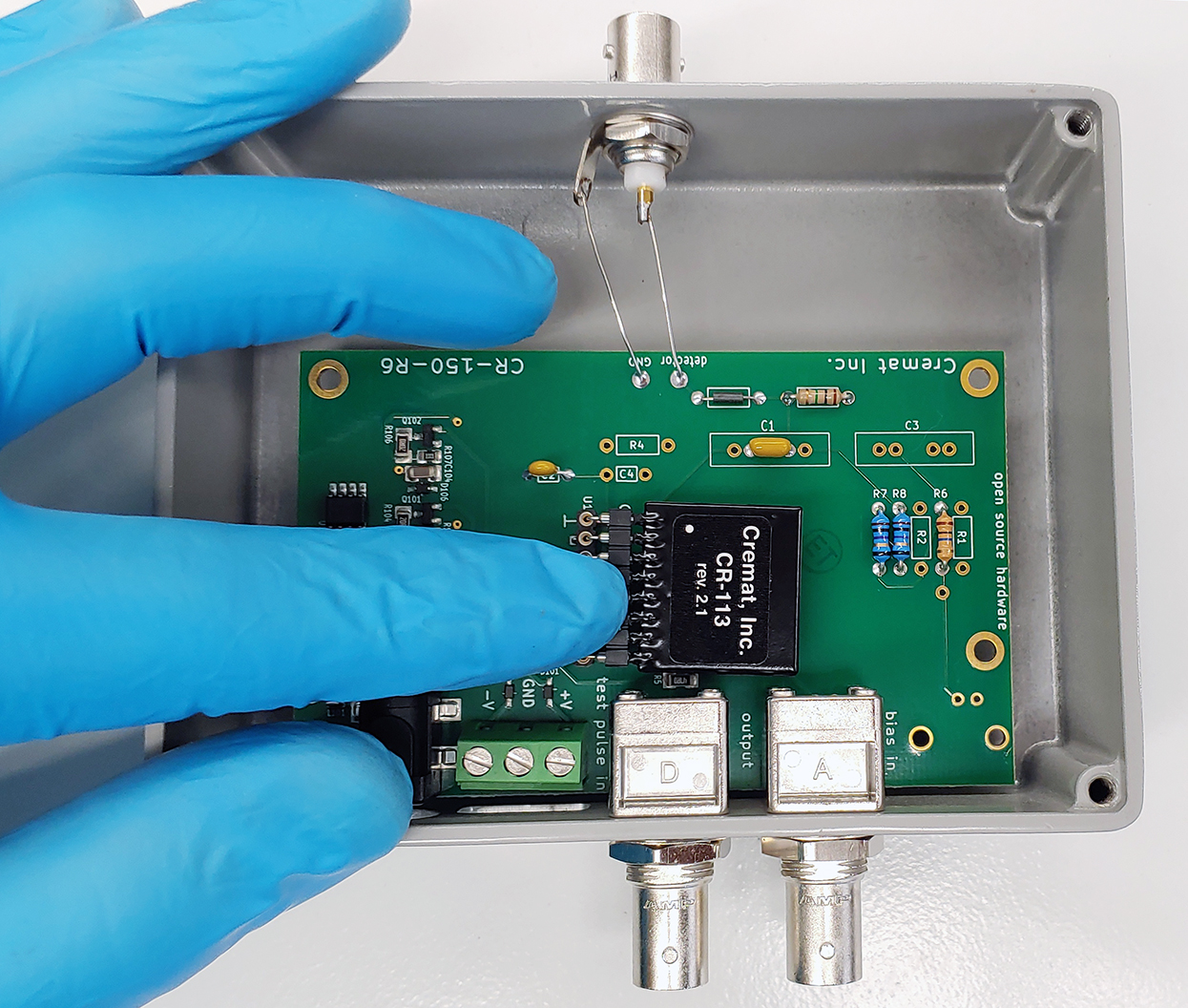
Completed assembly
Assembly complete after you fasten the lid!
