The charge sensitive preamplifier can be connected to the detector using one of two methods: 'AC' or 'DC' coupling.
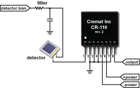
Using DC coupling, one leg of the detector is connected to the preamplifier input while the other is connected to a bias supply (most detectors require the application of a bias voltage, which creates the electric field inside the detector - necessary in most cases to generate the signal current). A diagram of a DC coupled circuit is shown here:

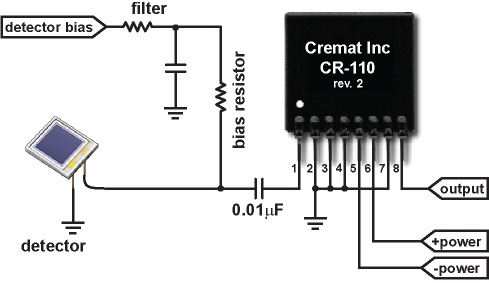
One of the drawbacks of the DC coupled detector is that the detector current (both the dark current and signal current) must be sourced or sunk by the preamplifier input. This results in a DC offset of the preamplifier output signal. In many cases the detector current produces an offset in the preamplifier output that is impractically large. To avoid this problem, most designers use AC coupling to connect the detector to the preamplifier. In this configuration, the DC detector current bypasses the preamplifier input and is instead supplied by a bias resistor. An AC-coupled circuit is shown below:

Cremat's CR-150-R6 evaluation board uses an AC-coupling scheme in part because of the improved performance with large detector currents. More information can be found in the specifications for the CR-150-R6.
Besides bypassing the detector dark current, there is a second advantage using AC coupling: the counting rate capability is increased. This is true if we use the simplifying assumption that the detector signal current is made of very many relatively small pulses. Using AC coupling, the DC (or average) detector current no longer passes into the preamplifier input. As a result, the preamplifier output saturates only when the output fluctuations become so large that they exceed the rail-to-rail output range of the preamplifier. The size of these fluctuations depend on the size distribution and rate of the detected pulses, and it is difficult to quantitatively describe the count rate limitations of the preamplifiers under these conditions. To generalize, however, we can say that the AC coupled detector has improved count rate performance over the DC coupled version.
There are two possible disadvantages of using AC coupling. The first is that the decay of the preamplifier signal has two different decay times when using AC coupling. The first is the decay time of the preamplifier (for the CR-110 this figure is 140 microseconds). The second decay time is the slower decay of the coupling capacitor times the bias resistor. This decay time is on the order of one second. So if the shape of the signal at very long times is important, then you must consider the extra decay of due to the coupling capacitor. In almost all applications this is not important, however.
The second possible disadvantage of using AC coupling is that the 'bias resistor' (on the CR-150-R6 board this resistor is valued 200 megohms) is a source of thermal electronic noise. Careful choice of the value of this bias resistor, however, can reduce the magnitude of this noise so that it becomes negligible. If the detector current produces a voltage drop of at least 0.5 volts across the bias resistor, then the shot noise from the detector leakage current dominates the noise and the thermal noise of the bias resistor is comparatively small. Choosing the bias resistor value does, however, require some approximate knowledge of the detector current. The product page for the CR-150 evaluation board contains a table which may assist in selecting bias resistor values.