A common question regards the output polarity of the preamplifier signals.
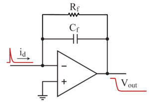
Current pulses from the detector flowing into the preamplifier input will produce negative output pulses, and vice versa.

In the above schematic drawing, the charge sensitive preamplifier (CSP) is drawn as an opamp with feedback resistor and feedback capacitor. This is a simplified model of a CSP, however analysis of this diagram provides the clearest explanation of the CSP output polarity.
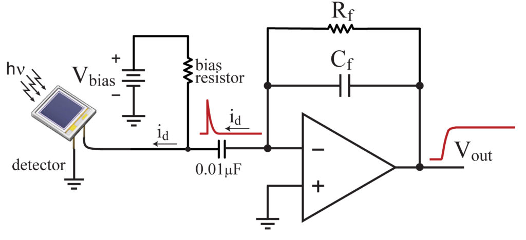
When a CSP is used in an 'AC-coupled' circuit (e.g. the CR-150-R6 evaluation board), the polarity of the output signal is shown in the circuit below:

A good rule of thumb is that the polarity of the output pulses is the same as the polarity of the applied bias in an 'AC-coupled' circuit. Note that the current pulses from the detector flow from the CSP input in the above diagram.
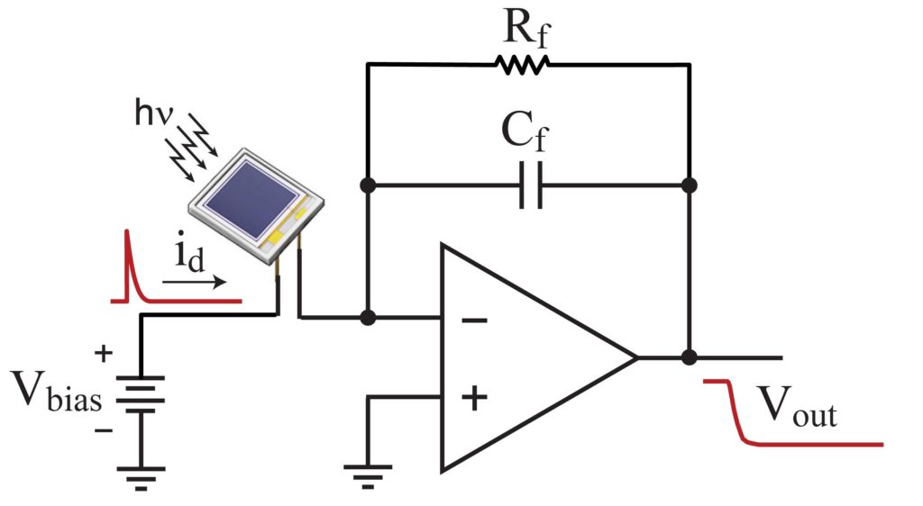
Things are different when a 'DC-coupled' circuit is used. The circuit below shows such a DC coupled detector used with a positive bias source. In this case the current pulses from the detector flow into the CSP input, causing the output polarity to be negative. Of course, if one were to use a negative bias source the CSP output pulses would be positive.

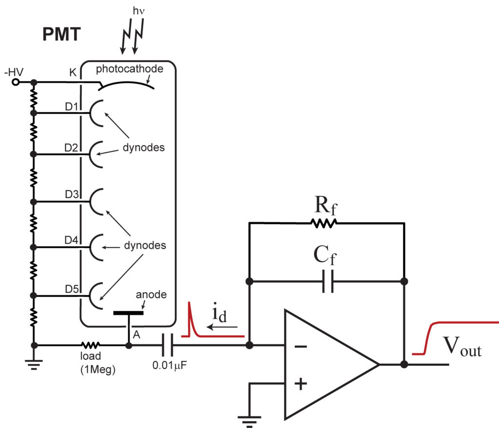
In the case of PMT readout, the output of the CSP is always positive. This is because current always flows from the PMT anode to the photocathode (in an opposite direction from the negatively charged electrons). The result is that the current pulse is from the preamplifier input. This is illustrated in the diagram below:
